Avionics Bay
Lower Stack
3 third-shells · #6-32 bolts · Al 6061
Structural Mass
9.07 lb
Mass Budget
16 lb
Design Load
3500 lbf
Press Tested
6000 lbf
OD Limit
8 in
Design Concept
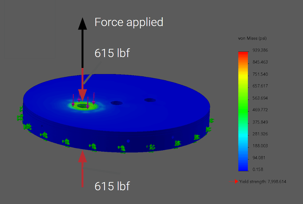
The third-shells carry all compressive loads independently, no internal structure needed for support. Two stacked disks mount inside and slide out when a shell is removed, giving clean access to avionics without disturbing the structure. The shells survived 3 tons in a hydraulic press, well above the 3500 lbf flight requirement.
Objectives
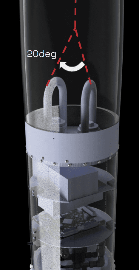
House avionics & ox tank forward valves
Withstand 3500 lbf compressive during static fire & flight
Low cost, easy avionics access
Quick to manufacture & integrate
Minimize mass to offset other systems
Constraints
16 lb total budget (9.4 lb structural worst case)
Stay within 8" OD
Bolts sourced from Bolt Depot only
Max 3× ½-20 threads on dome interface
Lower Stack Requirements
FCRemovable with one shell removed
FCDamp vibration from flight computer
SealPrevent fluid ingress from valves below
ThermalDissipate heat from flight computer


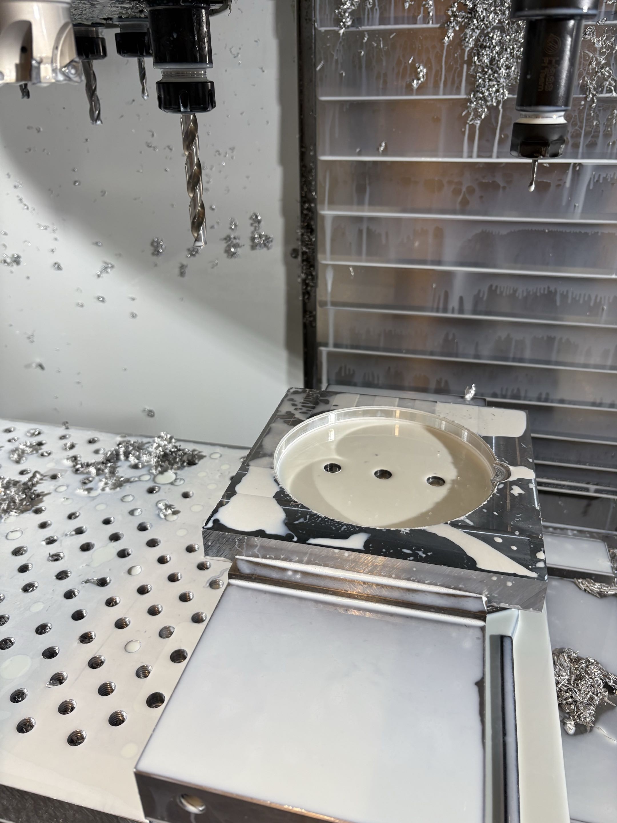
4-axis radial drilling on the Haas, A-axis CAM setup