SystemTrane CGAM-26 commercial air-cooled chiller serving the BU College of Communication. Vapor-compression refrigeration cycle using R410A refrigerant.State 1→State 2→State 3→State 4→State 1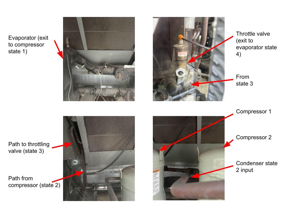 Trane CGAM-26 with state labels — evaporator, throttle valve, compressors, and condenser identified on site
Sensor Minimum
Trane CGAM-26 with state labels — evaporator, throttle valve, compressors, and condenser identified on siteSensor Minimum
- ·2 thermocouples — States 2 and 3 (State 1 doubles for State 4)
- ·2 pressure transducers — high-side and low-side
Key Components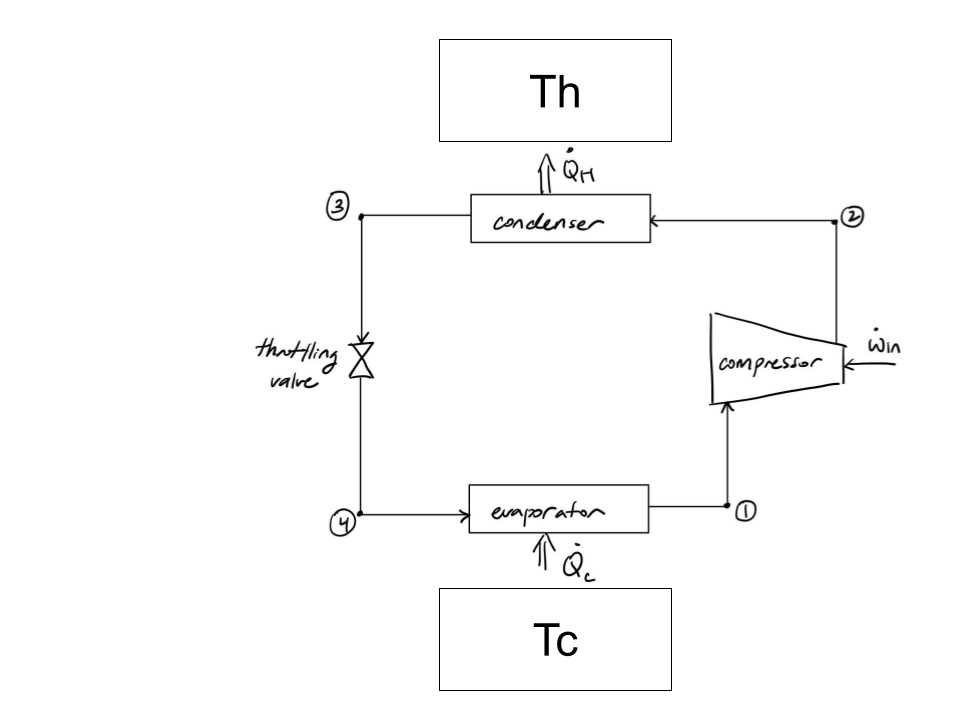 Vapor-compression cycle schematic — condenser, compressor, expansion valve, and evaporator with energy flows Q̇_H, Q̇_C, and Ẇ_in
Thermodynamic States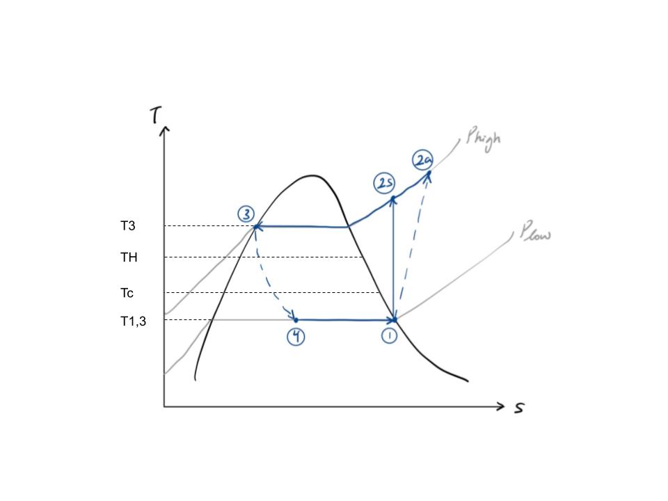 T-s diagram — states 1–4 plotted on the R410A vapor dome with high- and low-pressure isobars
- ·Compressors (×2) — staged for redundancy and variable load
- ·Condenser — rejects heat to outdoor air via axial fans
- ·Expansion valve — isenthalpic throttling, reduces T and p
- ·Evaporator — absorbs heat from water-glycol building loop
Vapor-compression cycle schematic — condenser, compressor, expansion valve, and evaporator with energy flows Q̇_H, Q̇_C, and Ẇ_inThermodynamic States
- ·State 1 — saturated vapor, evaporator exit, low p
- ·State 2 — superheated vapor, compressor exit, high p
- ·State 3 — saturated liquid, condenser exit, high p
- ·State 4 — two-phase mixture, expansion valve exit, low p
T-s diagram — states 1–4 plotted on the R410A vapor dome with high- and low-pressure isobars