Off-Road Suspension

Goals Redesign the full Brake, Suspension, and Steering systems for a new four-wheel, single-driver competition vehicle from the ground up. Primary targets included a minimum 30% reduction in turning radius from the previous year's unwieldy ~7m baseline, structural systems capable of surviving 4 kN+ dynamic loads across extreme terrain while maintaining a wide range of suspension travel, and a fully parametric architecture that could be tuned and customized rapidly between competition events
AssembliesCAMDesign for Manufacture (DFM)FEAGD&TMechanismsOnshapeStructuresManufacturing Processes
Head of Brakes, Suspension, and Steering Systems: Led design and development of all BSS subsystems, delegating tasks across the team and verifying design integrity through FEA. Coordinated with manufacturing to implement DFM principles across all components
Sep 2024 - June 2025
Project CompleteRedesigned all Brake, Suspension, and Steering systems into a fully parametric master assembly, enabling real-time geometry recalculation from toe, camber, and compression inputs, eliminating pre-manufacturing fit failures. Led the front hub carrier transition from MacPherson strut to double wishbone, designing and CNC milling custom carriers on a 3-axis HAAS to withstand upwards of 4 kN at a safety factor of 4, validated in both ANSYS and SolidWorks. Final parts achieved ±0.005" overall tolerance with ±0.001" on the bearing bore for interference fit. Led cost-saving initiatives that cut $3,000 in expenses through in-house CNC fabrication and DFM optimization. Systems were proven to endure rollovers and extreme dynamic loads in competition
Redesign Brake, Suspension, and Steering systems from scratch for a competition vehicle. Targets: 30%+ reduction in turning radius from a 7m baseline, structural survival under 4 kN+ dynamic loads, and a fully parametric architecture tunable between events.
AssembliesCAMDesign for Manufacture (DFM)FEAGD&TMechanismsOnshapeStructuresManufacturing Processes
Head of Brakes, Suspension, and Steering Systems: Led design and development of all BSS subsystems, delegating tasks across the team and verifying design integrity through FEA. Coordinated with manufacturing to implement DFM principles across all components
Sep 2024 - June 2025
Built a fully parametric master assembly with real-time geometry recalculation from toe, camber, and compression inputs. Led MacPherson-to-double-wishbone hub carrier transition, CNC milling custom carriers to 4 kN at SF 4, validated in ANSYS and SolidWorks. Achieved +/-0.005" overall tolerance, +/-0.001" on bearing bore. Cut $3,000 in costs through in-house fabrication and DFM.
+
Steering Packaging
New rack and pinion with vertically-oriented tie rods to preserve wheel geometry. Wishbone arms sit forward of the linkage, so they take rock impacts first. The U-joint allows steering column clearance with the differential.
+
Hub Carrier
CNC milled on 3-axis HAAS. ±0.001" bore for bearing interference fit.
(Scroll down for more info)
+
Double Wishbone
Replaced a single MacPherson strut with two independent wishbone arms for better wheel control. Pickup points land on existing tube joints — no added bracing. Arms are flat sheet metal with alignment tabs, batch-cuttable on a waterjet.
+
Rear Suspension
The previous year's control arm bent at the rear under hard landings. Added triangular gussets at the failure points, routed clear of the shock and wheel carrier, with welded joints connecting everything. Mounting geometry is parametric -- input target wheel angle, model positions the control arm automatically.

Hub Carrier Project

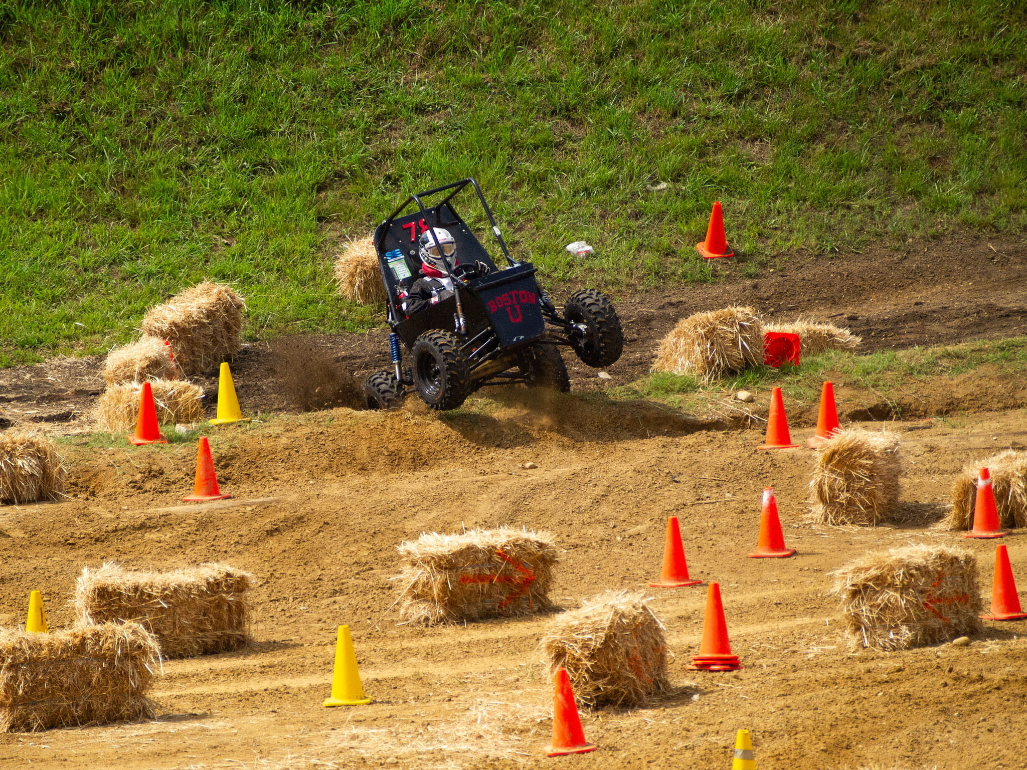
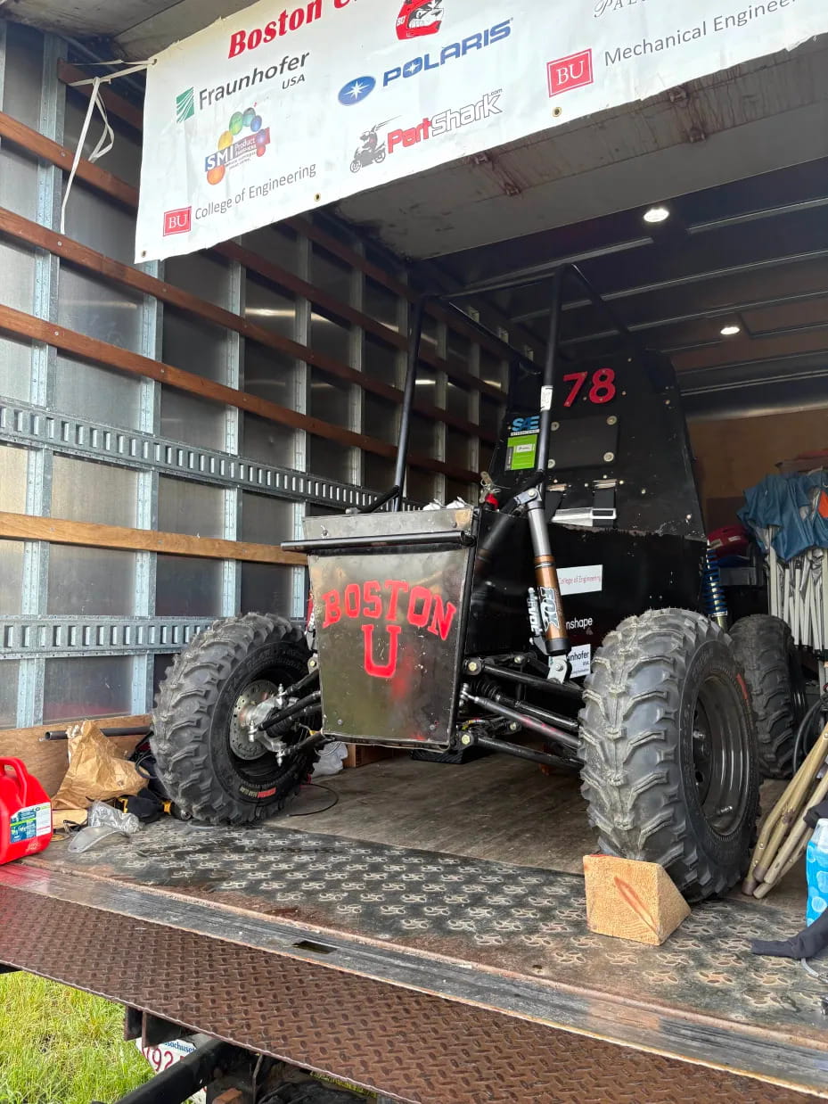
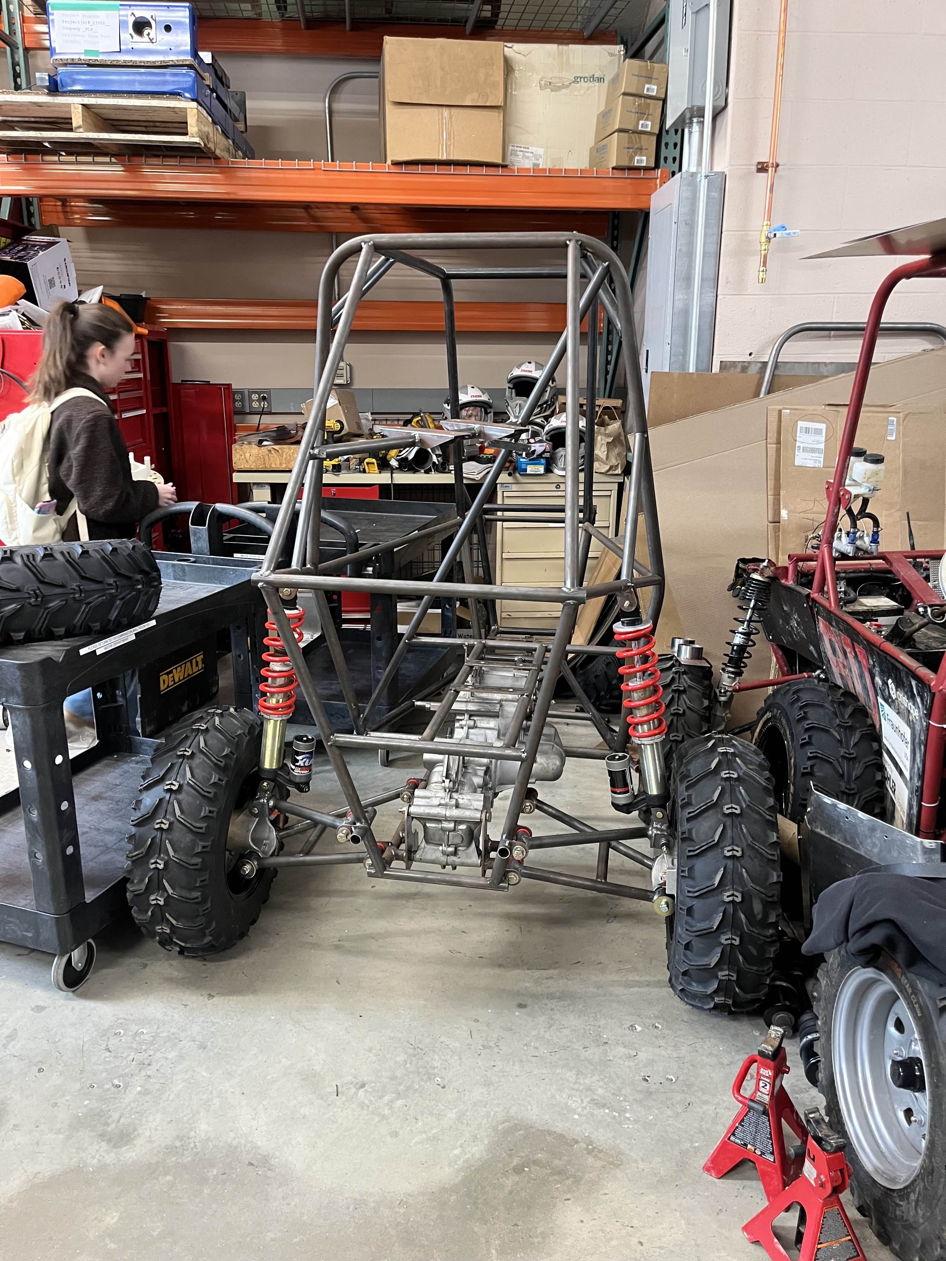
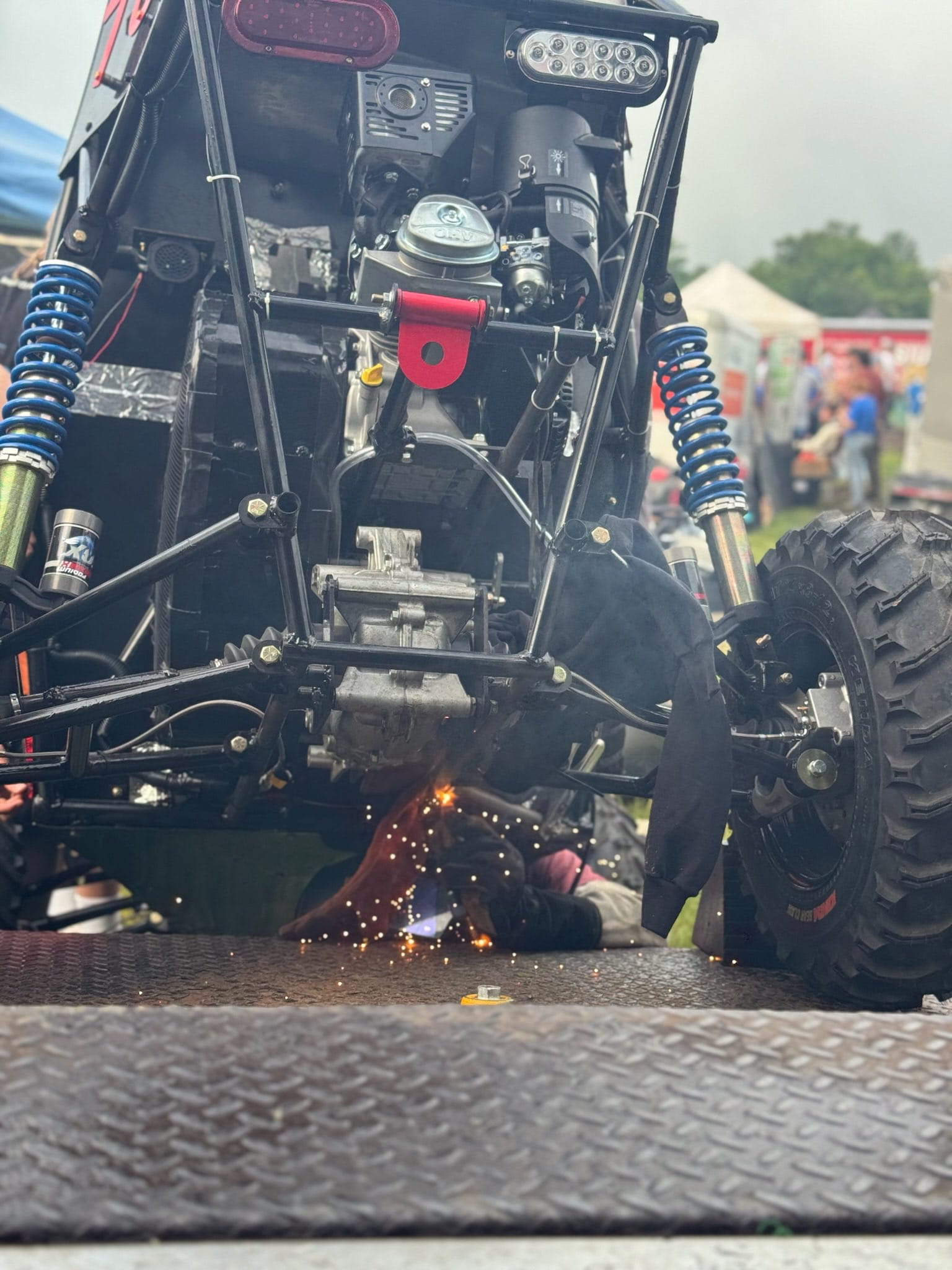
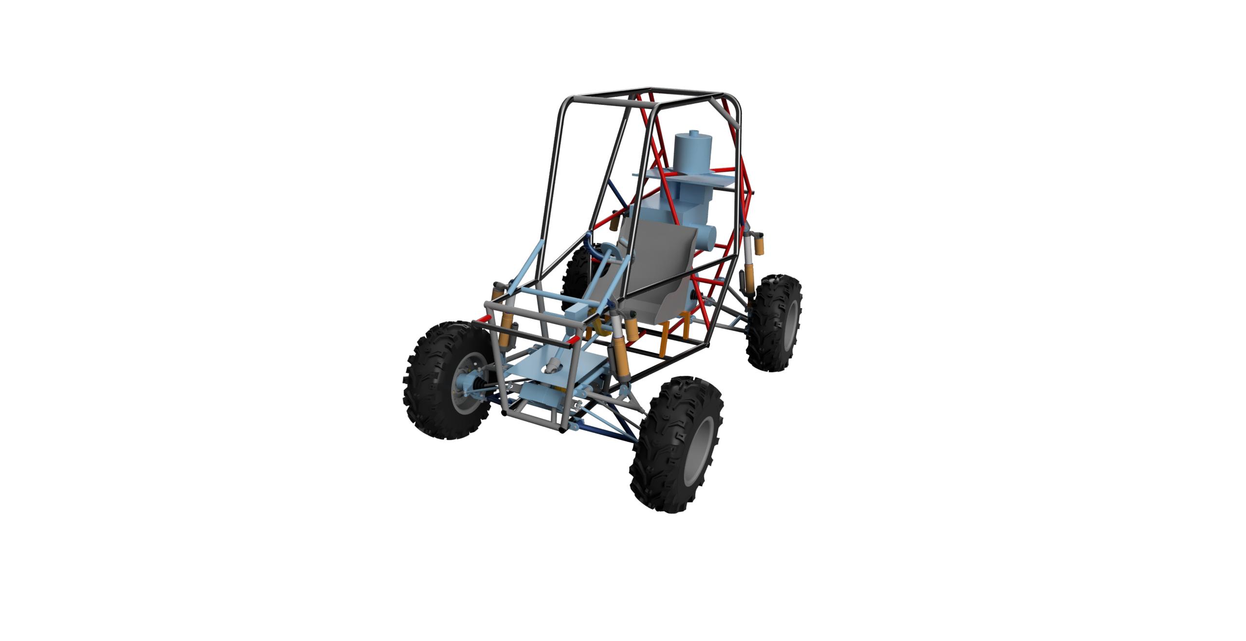
Previously, the team used a MacPherson strut setup for the front suspension, with the shock strut doubling as the upper suspension member. While compact, this limits independent geometry tuning and produces poor camber change through travel, causing the tire to lose contact patch on rough terrain. I redesigned the front suspension to a double wishbone layout, giving direct control over camber gain, roll center, and scrub radius. The geometry change meant our existing axles, brake calipers, and wheels no longer had a compatible interface to the new suspension. I designed, mechanically validated, and CNC machined two 6x6x7" aluminum hub carriers to integrate the bearing, brakes, axles, and wishbones into the new configuration.

MacPherson Strut

During the initial design phase, structural finite element analysis (FEA) was conducted to ensure the part could withstand a reasonable load case of 5 kN. The final component achieves a safety factor of 1.4. Results were cross-validated using both ANSYS and SolidWorks.

Finite Element Analysis, pink arrows depict bearing load and green washer contact surfaces on the ears are pinned

Because dimensions for our brake calipers are not listed, I used 3D prints to make sure the spacing of the mounting holes was correct.

3D print test piece check with caliper

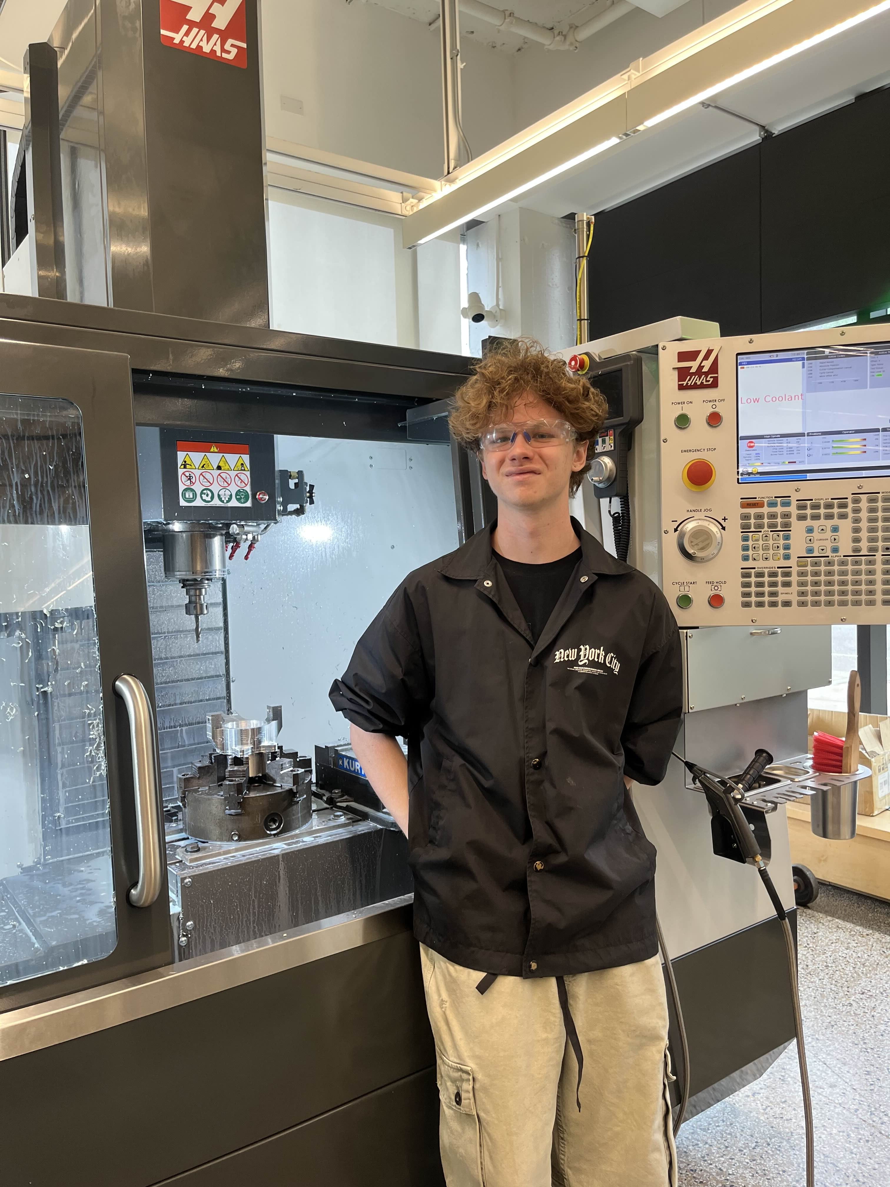
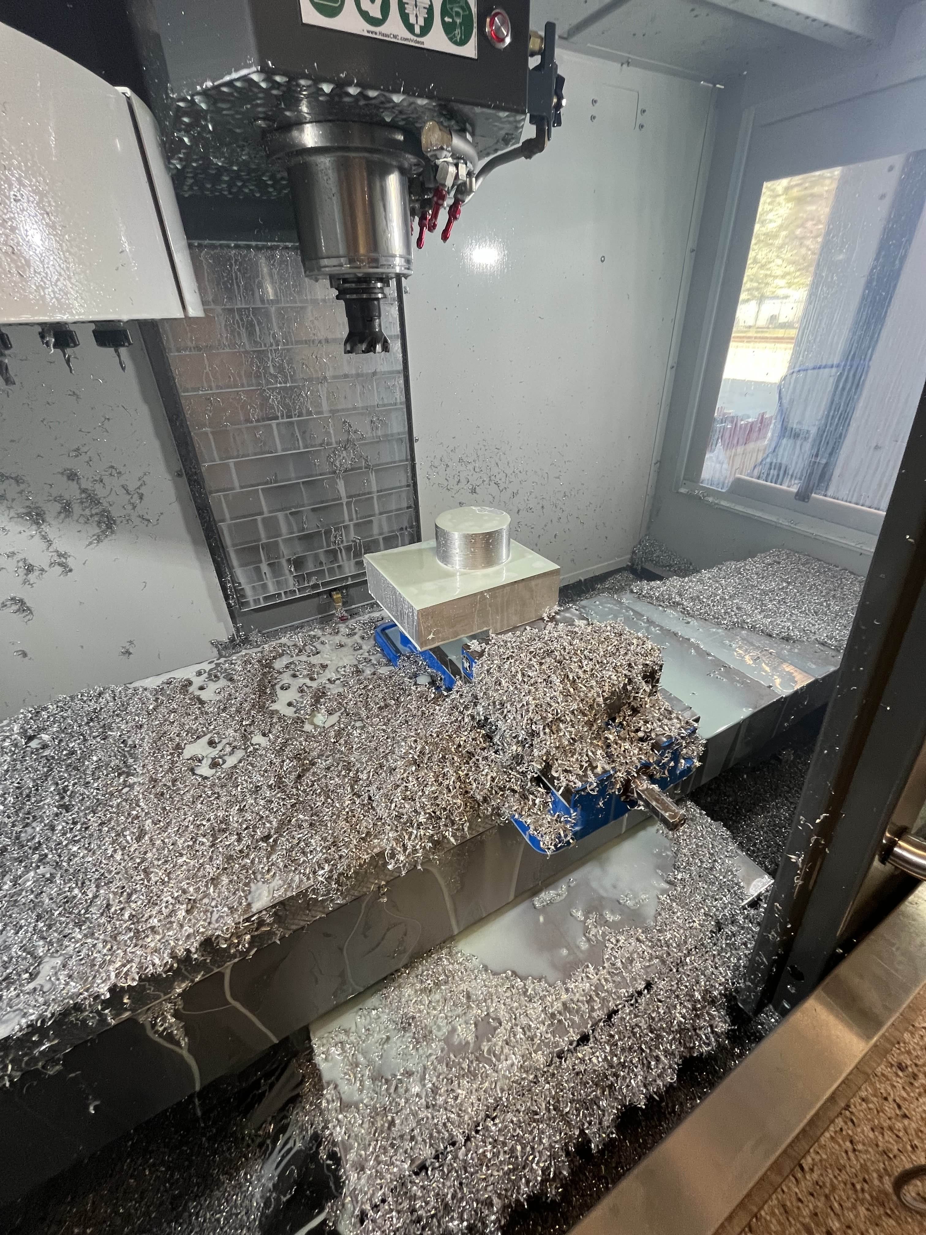
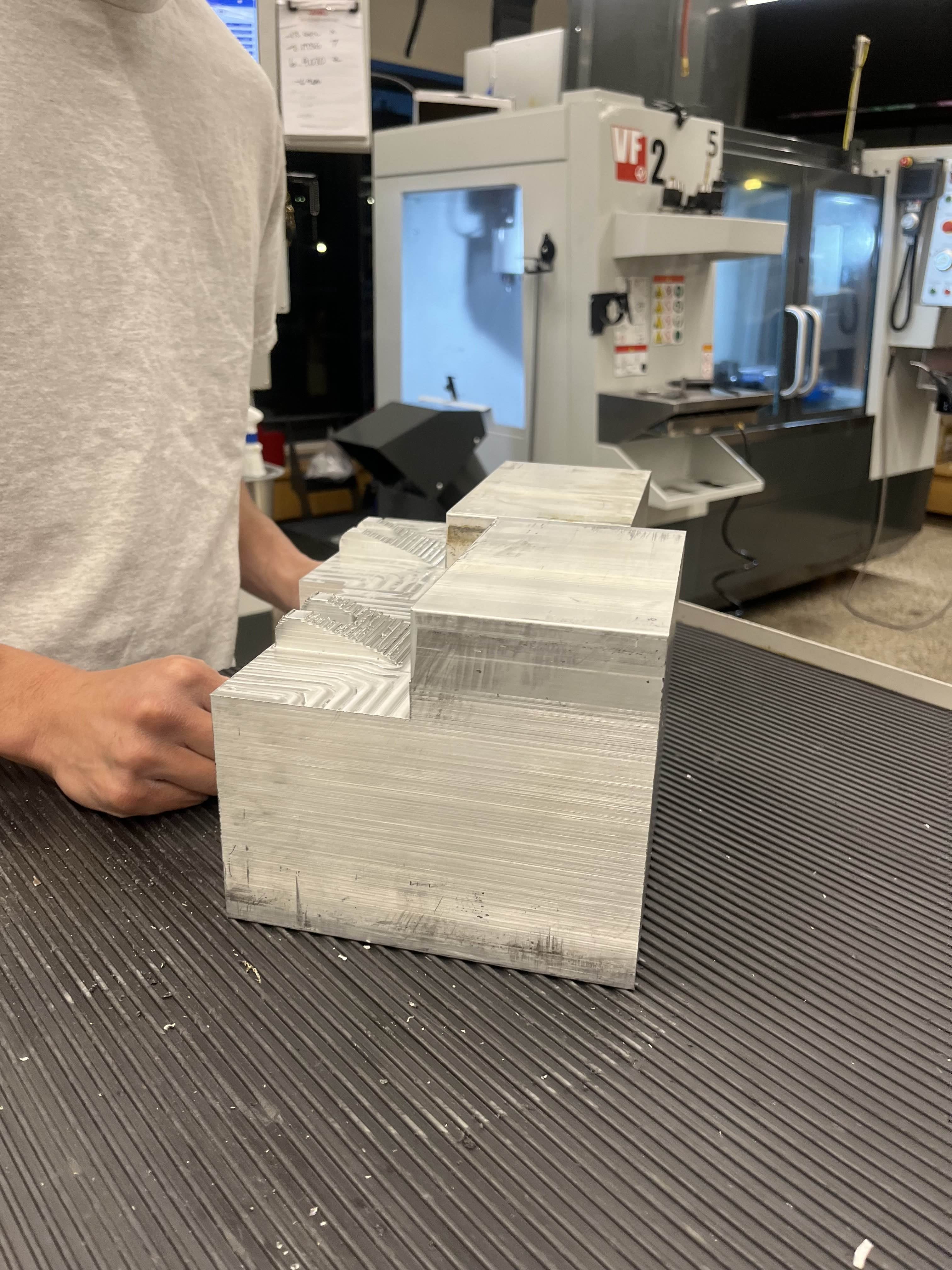
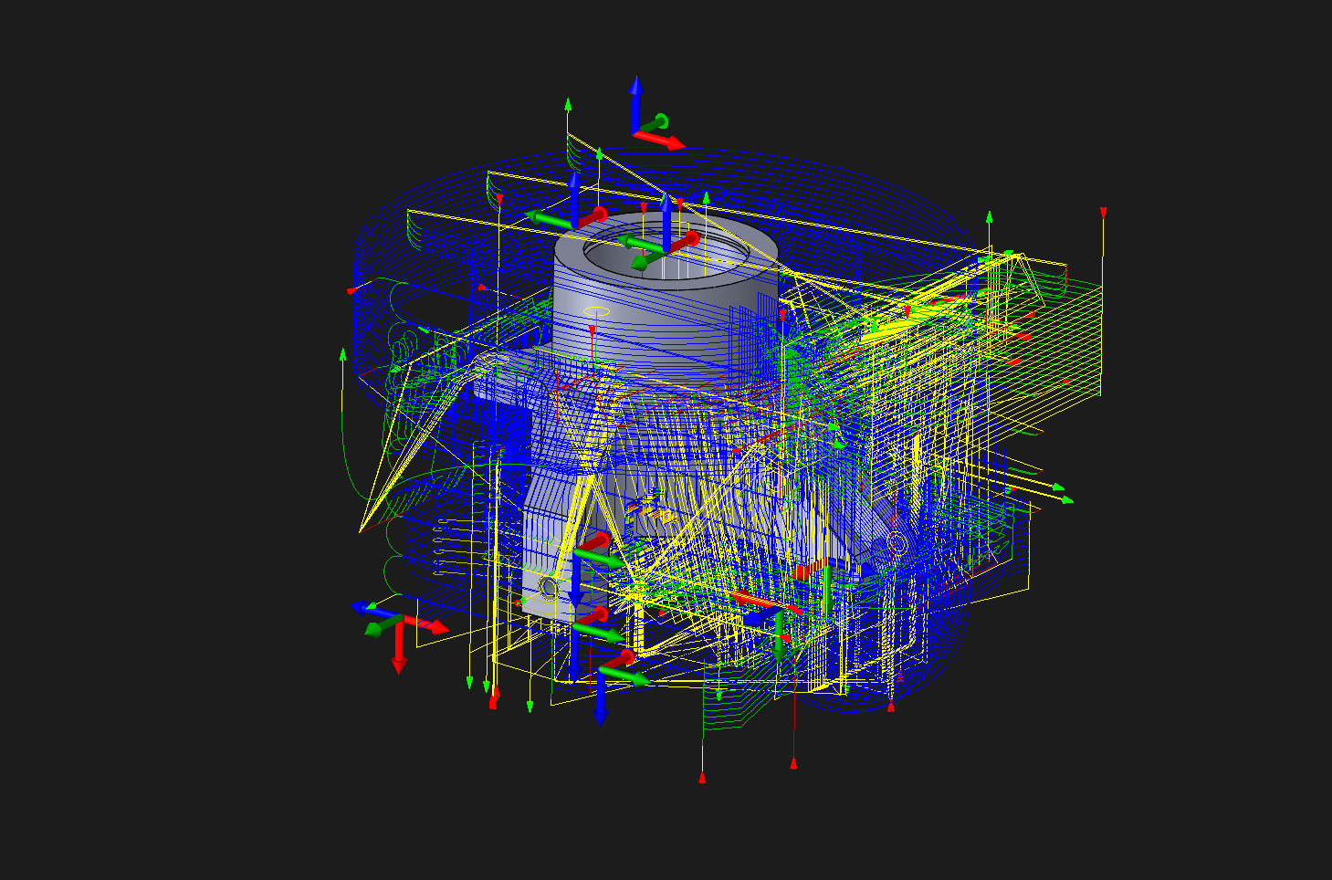
CAM was completed in SolidWorks/HSMWorks across 10 setups, with operations sequenced around a rectangular fixturing section to avoid custom clamps entirely. 3-axis was fine for a two-part run but would hit real limits at scale. Toolpaths were validated against actual tool geometry, especially for the final bore which needed a bearing interference fit.


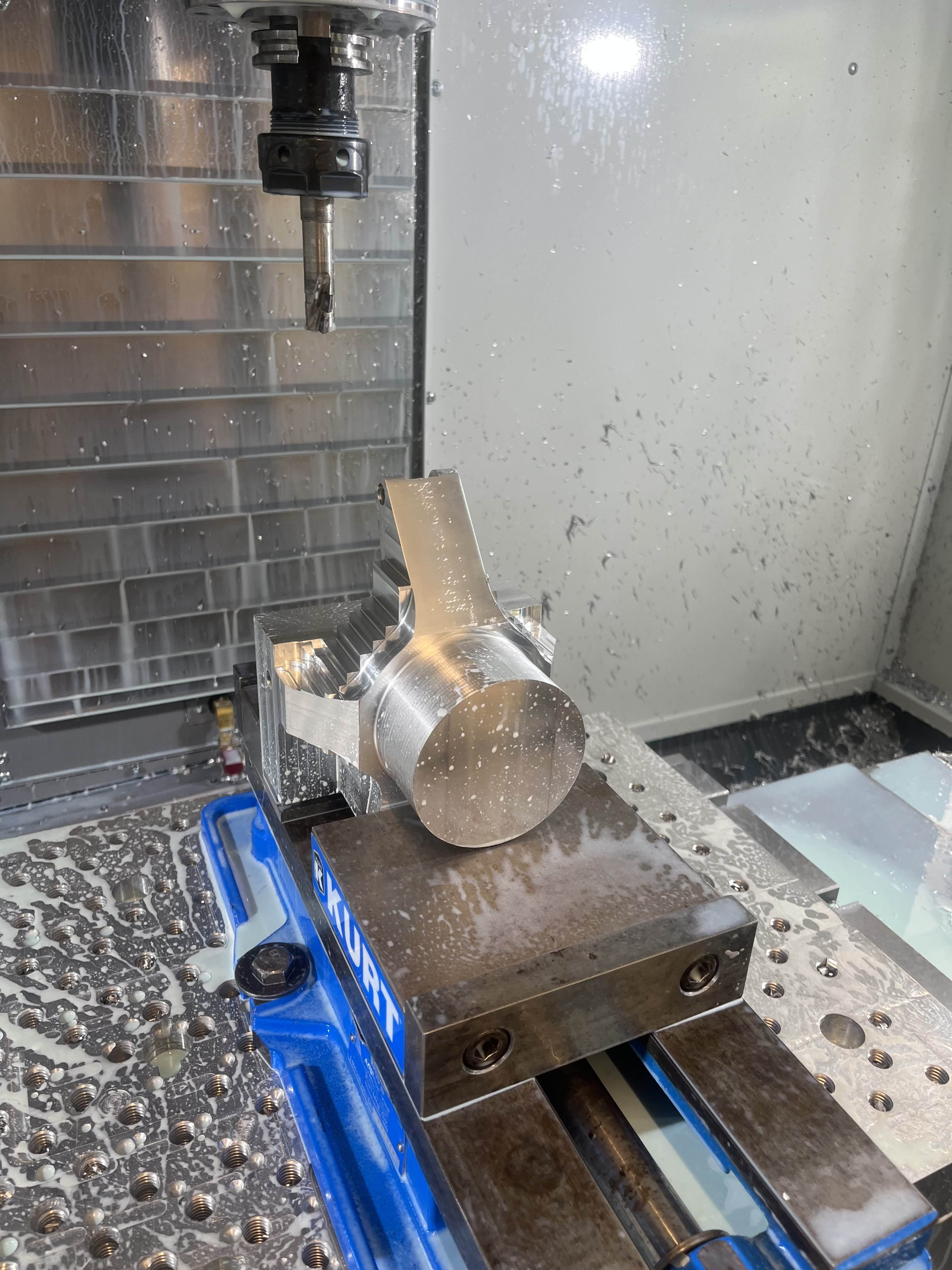
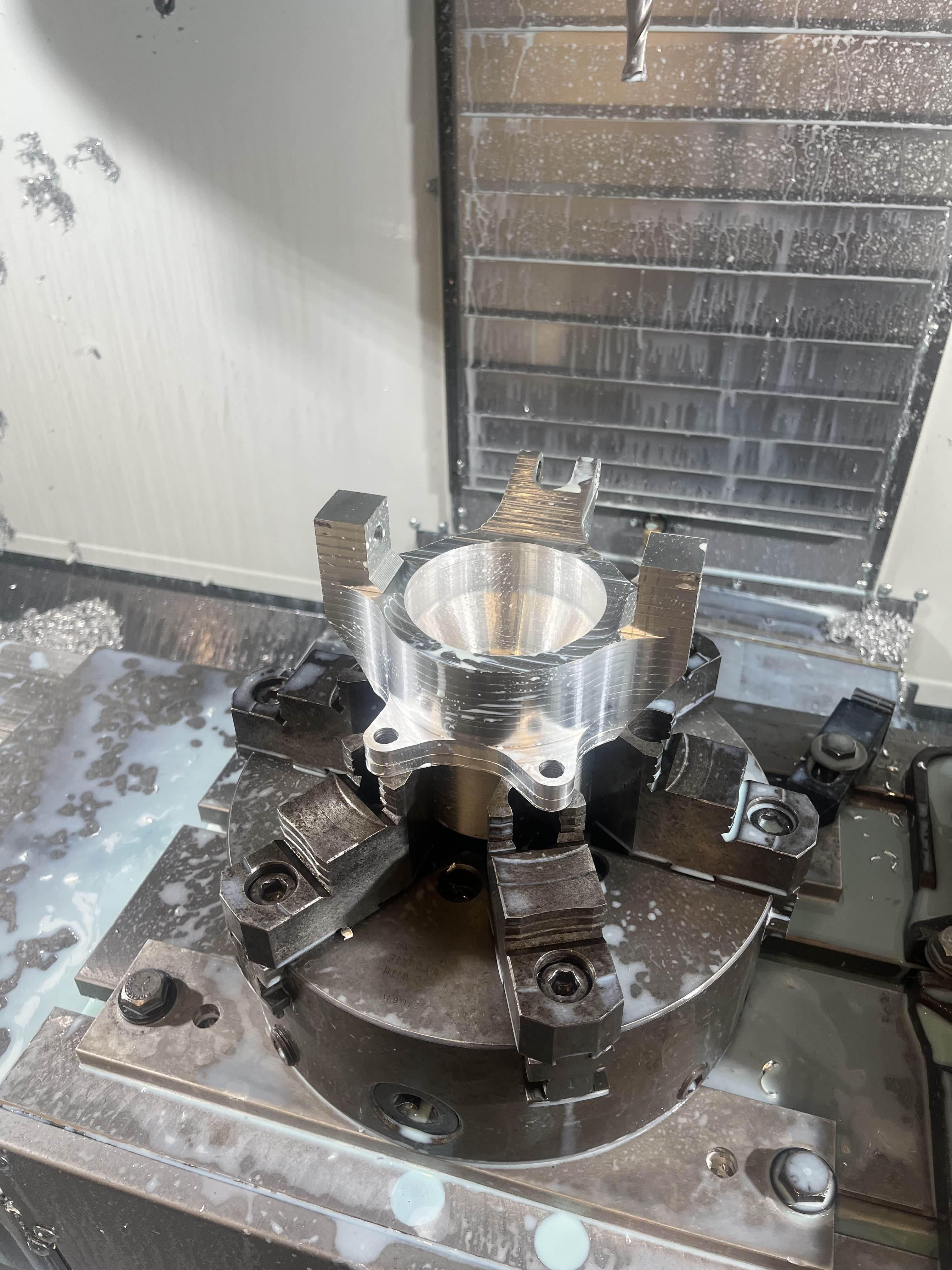
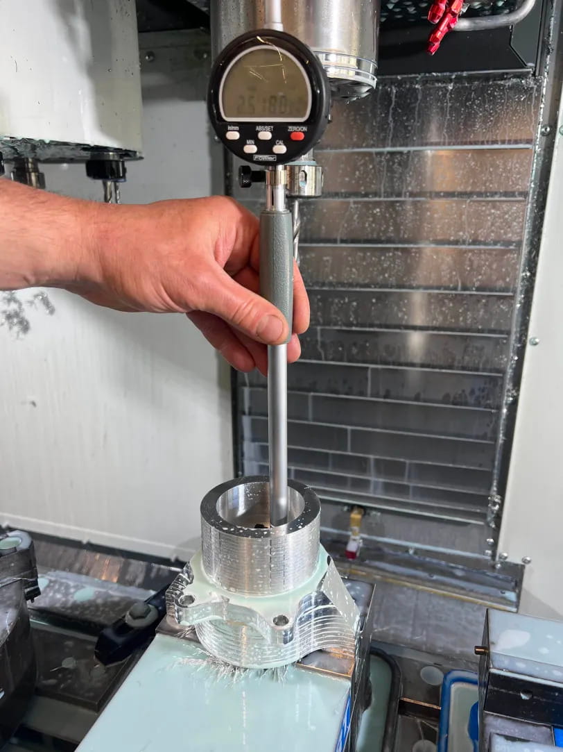
Machining was developed through direct mentorship from machinists with 30+ years of experience, with design reviews before any material was cut. The practical stuff: climb cutting for finish quality, helical entry to protect tooling, and chip evacuation forcing operation order in ways CAM software never flags. Measuring between every setup caught fixture shift before it compounded. The bearing bore required an interference fit, so the final phase required multiple finishing passes with dial indication checks.


The bigger takeaway was that sequencing is a structural decision. Rough while the part is rigid, finish after geometry stabilizes, tolerance-critical features last.

SolidWorks CAM stock simulation. Red areas are rounding errors where the tool flange touches the material

Results

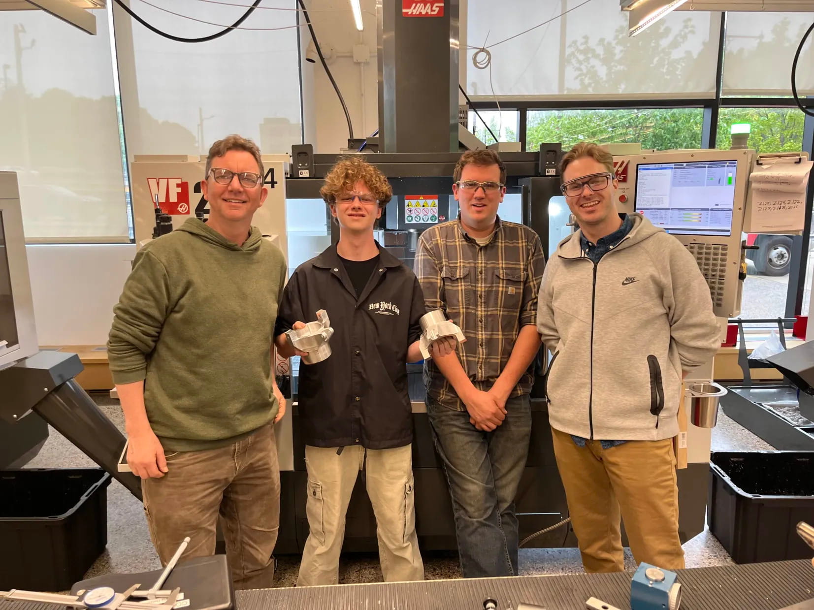
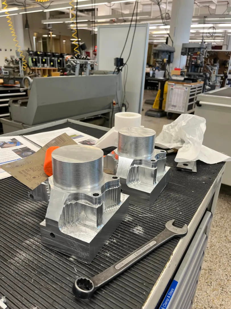
Two custom hub carriers were successfully milled and integrated into the vehicle. The parts achieved ±0.005" overall tolerance, with ±0.001" precision achieved on the bearing bore to meet tight interference fit requirements.