


How the GA works:
Initialize the fin to our baseline design from a previous rocket
Set bounds for each parameter, eg thickness can be between .293” and .4”
Generate 50 fin designs with random modifications to each parameter
Take 12 fins with lowest drag while having flutter > mach2.68
Take these elite 12 and randomly vary each one, again taking the 12 best performers
Stop when the drag stops reducing or maxGenerations is hit
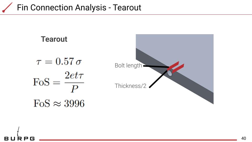
Load cases
In-house manufacturing is limited to 3-axis CNC, meaning the double-wedge cross-section cannot be achieved by tilting the head — instead, large-diameter face cutters are used for the flat angled faces and ball end mills handle the leading and trailing edge radii. This constraint makes surface finish a critical design consideration.

Even at 5 thou stepover with an endmill, already prohibitively slow, this yields ~127 µm surface finish, costing roughly 11,500 feet of apogee per OpenRocket simulation. This is conservative: in the supersonic regime each scallop cusp generates a local oblique shock, with expansion and recompression repeating across every pass transition, compounding wave drag significantly. To mitigate this, a large-diameter ball end mill was selected to maximize R and suppress scallop height without proportionally increasing pass count, with finishing passes run at reduced stepover only on aerodynamically critical surfaces: the leading edge radius and wedge faces. Climb milling was specified over conventional cutting to reduce rubbing, minimize work-hardening, and improve surface finish on the aluminum. The setup avoids dedicated fixtures entirely, with the fin secured directly to the table and machined in multiple phases, clamps repositioned between phases to expose previously obstructed surfaces.
