ARGO
Boston University Rocket Propulsion Group
-
Develop a robust structures system for Argo, designed to become the highest-flying liquid bipropellant rocket ever launched by a university team
Prioritize serviceability, modularity, and cross-team collaboration to streamline integration and maintenance throughout the rocket’s lifecycle
Encourage broad participation and mentorship to give more students hands-on exposure to advanced rocketry and cultivate the next generation of world-class engineers
-
Structures Engineer
-
Jun 2025 - Present
-
Solidworks
Structural Finite Element Analysis (FEA)
CNC Milling
Waterjet
Avionics
Fluids routing
-
Structures projects have been cleared with design reviews and are starting manufacturing
Teaching new members to use the Lathe & Mill at the Engineering Product Innovation Center
Separation +
Recovery
Objectives
Achieve reliable deployment of both drogue and main parachutes.
Keep It Simple (K.I.S.S.) — minimize mechanical and electrical complexity.
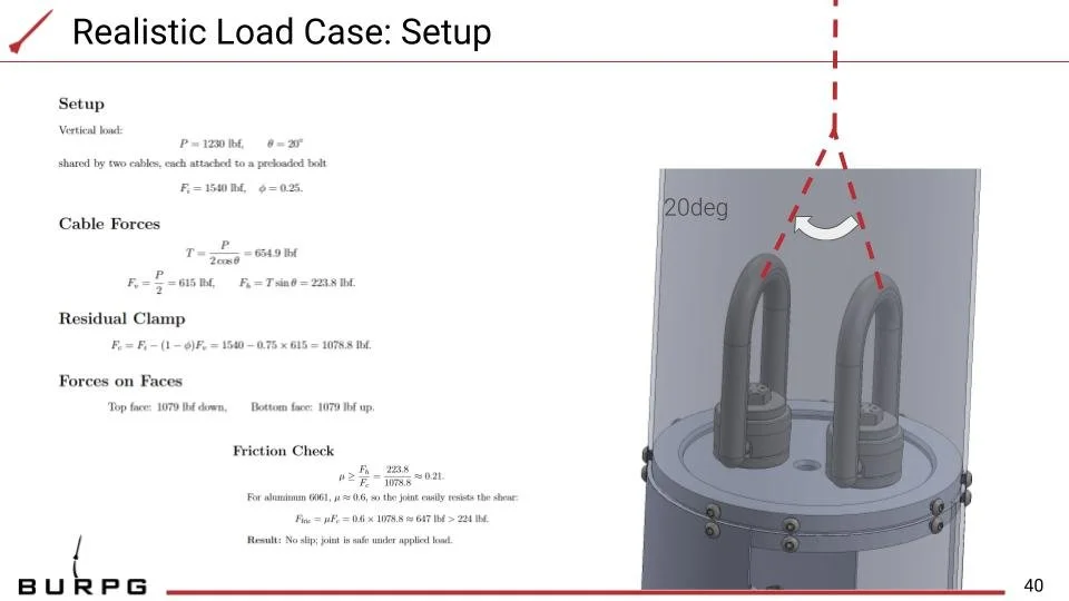
Ensure all components withstand deployment forces under worst-case loads.
Maintain space and clear routing for all connectors, charges, and recovery gear.
Integrate lessons learned from Icarus to maximize reliability and serviceability.
Functional Sequence
Launch → Apogee (~100 k ft):
Motor burnout and coast to apogee.Nose Cone Separation + Drogue Deployment:
Three black-powder charges and six e-matches (3 COTS, 3 FC). Drogue slows descent to ~118 ft/s to minimize drift.Main Deployment at 1500 ft AGL:
Two Tender Descenders + two cable cutters fire, releasing main parachute. Final descent rate ≈ 21.4 ft/s.
Avionics
Bay
Avionics Bay Requirement:
House all vehicle electronics, enable rapid removal for service, and provide sealed fluid routing from the dome systems that allows exhaust and maintenance access while preventing fluid ingress or upflow into the bay.
All electronics fit within defined clearances with direct tool access.
Quick-release fasteners and keyed connectors allow removal within the target service time.
Sealed feedthroughs and drains vent outward with no measurable ingress during pressure or splash testing.
This project marked my first experience with fluid line routing, focusing on a layout that enables easy serviceability, provides controlled exhaust where required, and ensures no leakage or fluid ingress into the avionics bay.


