Variable engine gaseous test stand

VEGAS

Boston University Rocket Propulsion Group

    • Design modular frame: Create a versatile frame that allows easy interchangeability of components for different engine types.

    • Modular mounts: Design adjustable engine, fuel tank, and propulsion mounts for quick engine swaps and adaptability.

    • Load cell integration: Incorporate high-precision load cells for accurate thrust measurement, with multi-axis support for vertical and horizontal force.

  • Structures Engineer

    • Onboarding – Hybrid Rocket Engine Development (Sep 2024 – Dec 2024)

    • Structures Engineer – VEGAS (Feb 2024 – Present)

    • Solidworks

    • Structural Finite Element Analysis (FEA)

    • Milling

    • Mechanical Design & Analysis

    • Machine Design

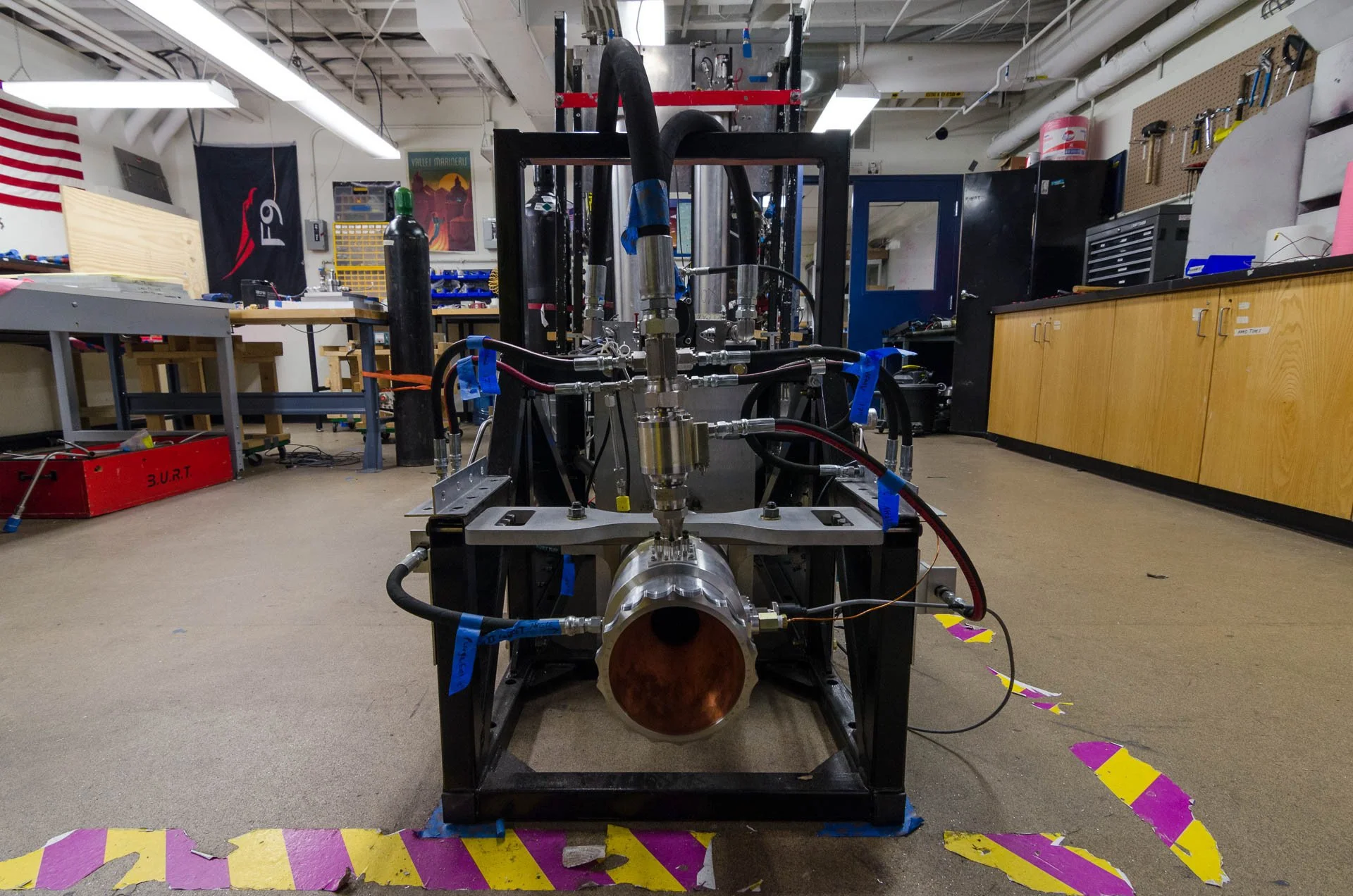
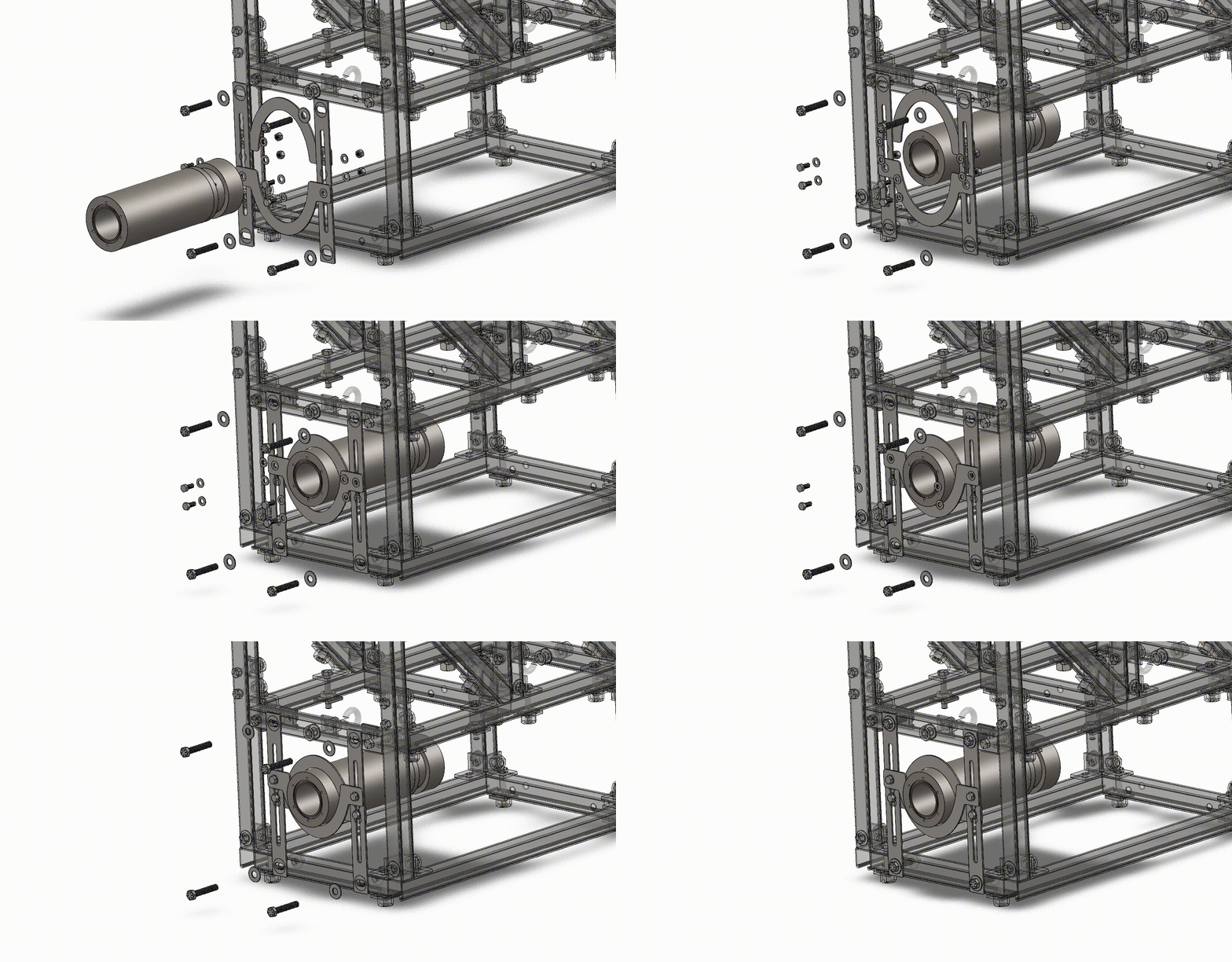
    • Designed and built a modular nozzle fixture integrating with existing fluid and fire-extinguishing systems.

    • Eliminated torque on the thrust-measuring load cell, ensuring accurate force readings and analysis for new engine systems.

    • Contributed to next-generation liquid propulsion development, supporting RPG’s efforts to become the first university team to launch a liquid-fuel rocket into space.

Current Development:

Horizontal Test Stand (HTS) - Predecesseor of VEGAS. I am currently designing avionics structures for its continued use.

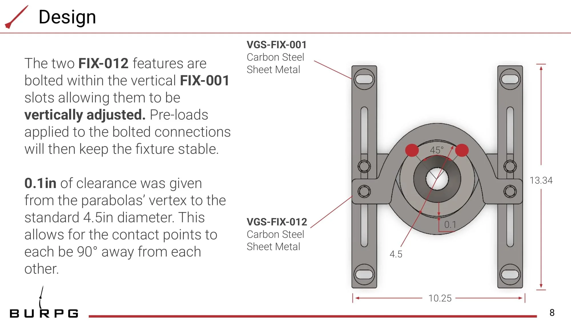
Engine Fixture

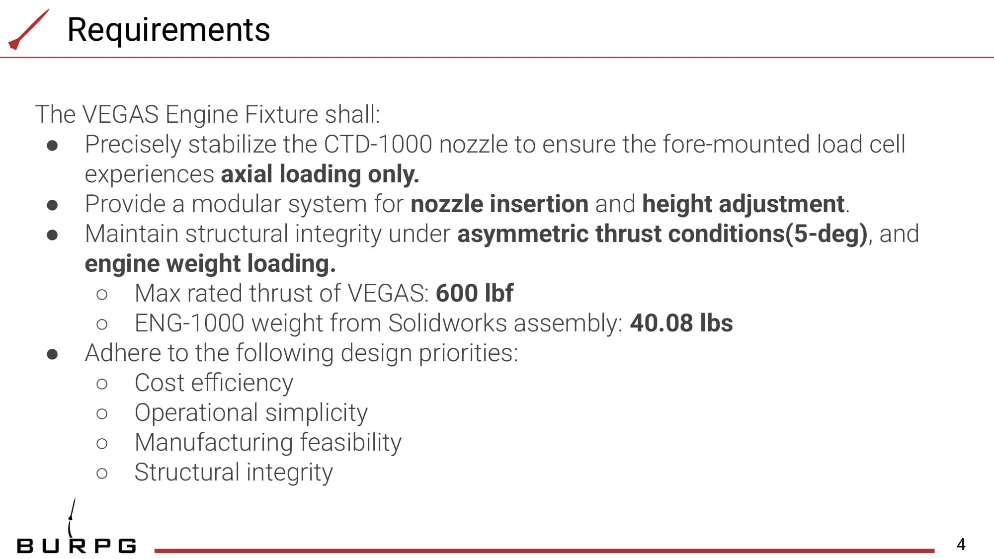
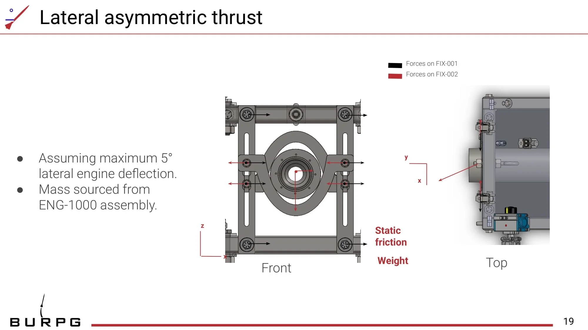
As is, the VEGAS test stand has expiremental nozzles mounted by their fore end onto a load cell. Due to the significant weight of the engines (40.08lbs for the current engine), and the possibility for assymetric thrust, this configuration is unstable and can lead to inaccurate load cell readings. Thus, I am developing the following fixture.

Structural Analysis and Manufacturing Approach for Nozzle Mounting Fixture

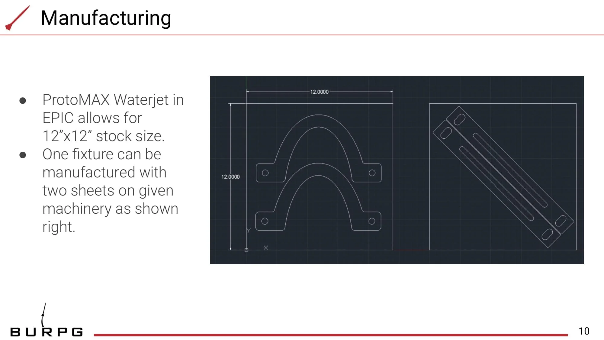
To enable modularity while maintaining manufacturability and cost-effectiveness, the assembly will be waterjet-cut from carbon steel. This material choice provides the necessary strength while ensuring efficient fabrication. The design spans a 14-inch gap across the VEGAS chassis, requiring careful consideration of structural integrity.

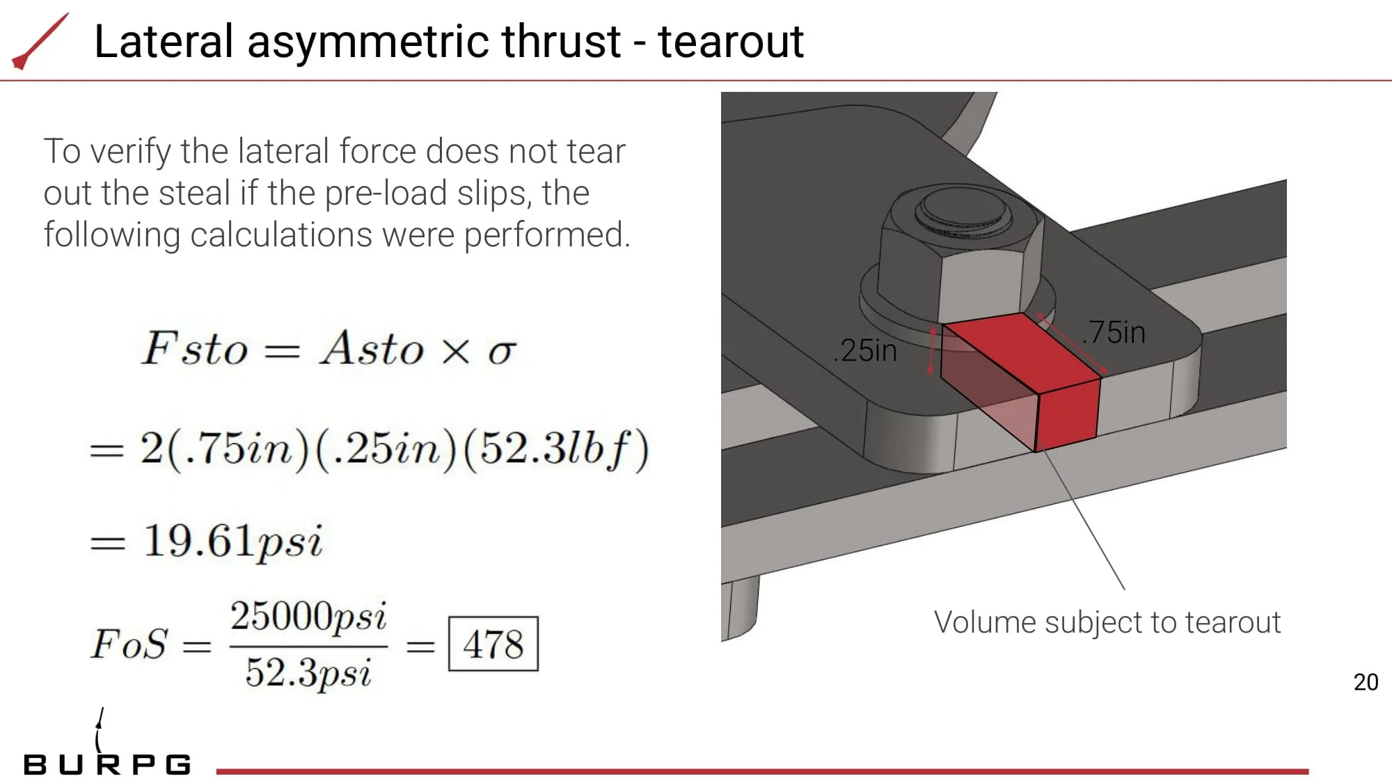
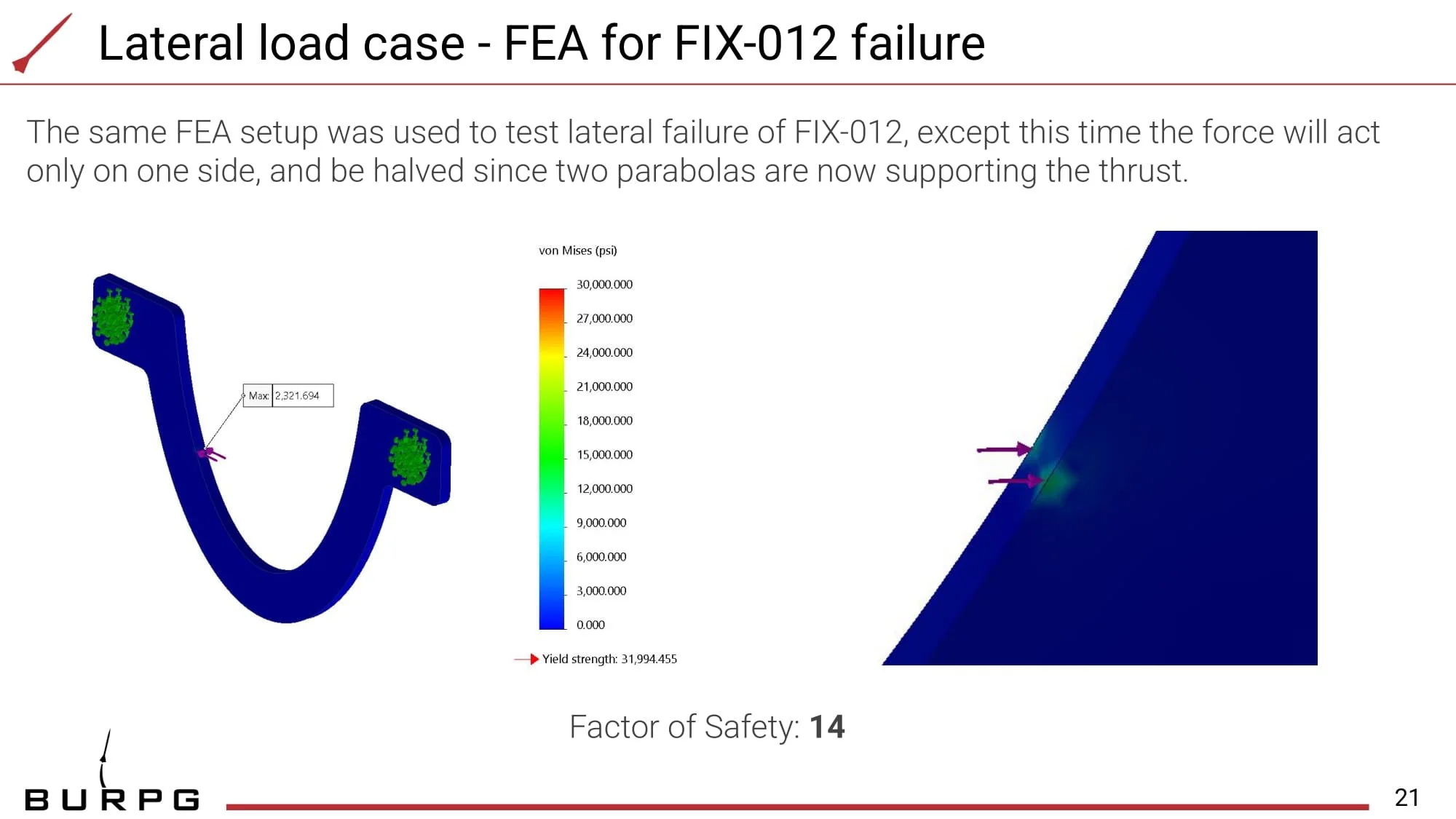
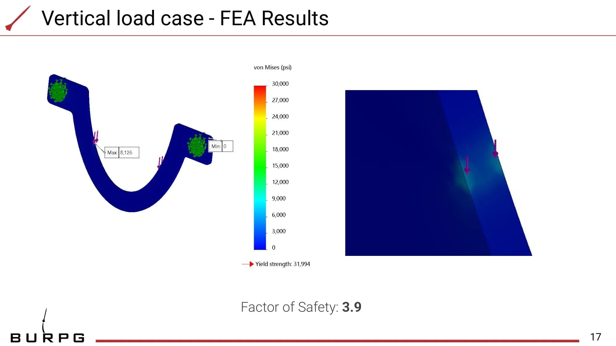
To ensure reliability, several load cases are tested, verified through Finite Element Analysis (FEA), reviewed in design evaluations, and cross-checked with hand calculations.

Worst-Case Load Scenario: Asymmetric Thrust + Nozzle Weight

The most critical failure mode occurs when both asymmetric thrust and the weight of the nozzle act downward. This scenario is optimized for structural integrity, considering the following potential failure mechanisms:

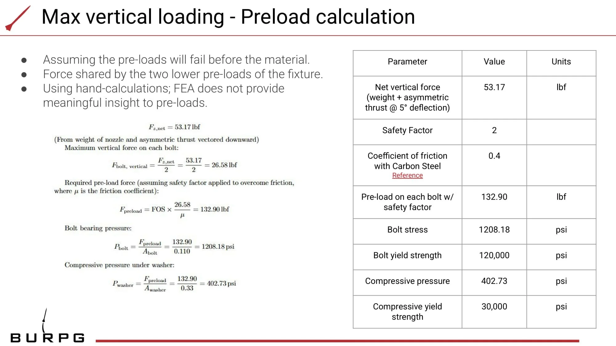
  1. Pre-load Failure

    • If the vertical force exceeds the static friction in the system, bolts may slip, leading to load cell misreadings and potential damage.

    • To prevent slippage, pre-loads were calculated so that the assembly withstands twice the rated force before slipping.

    • These values were verified to ensure they remain within the material limits of both the carbon steel structure and the bolts.

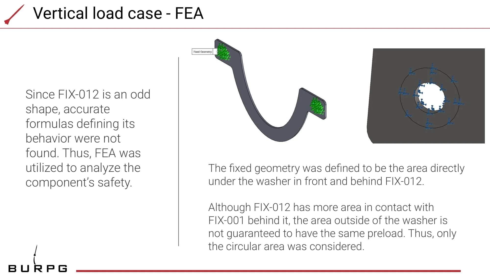
  2. Center Fixture Failure

    • If pre-load failure does not occur, the applied force from the nozzle could materially deform the fixture beyond its failure threshold.

    • FEA simulations and hand calculations confirm that the fixture maintains structural integrity under worst-case loading.

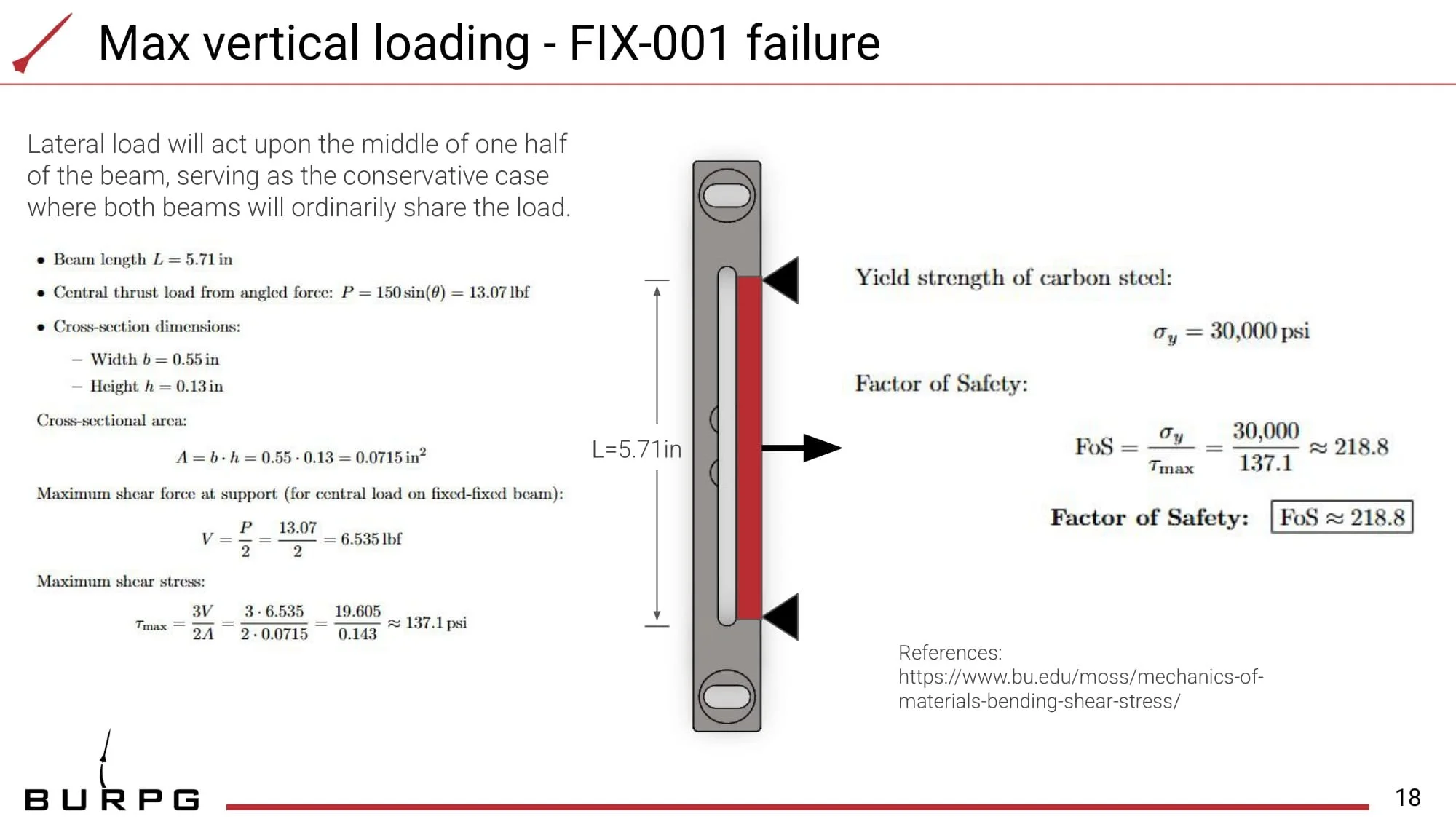
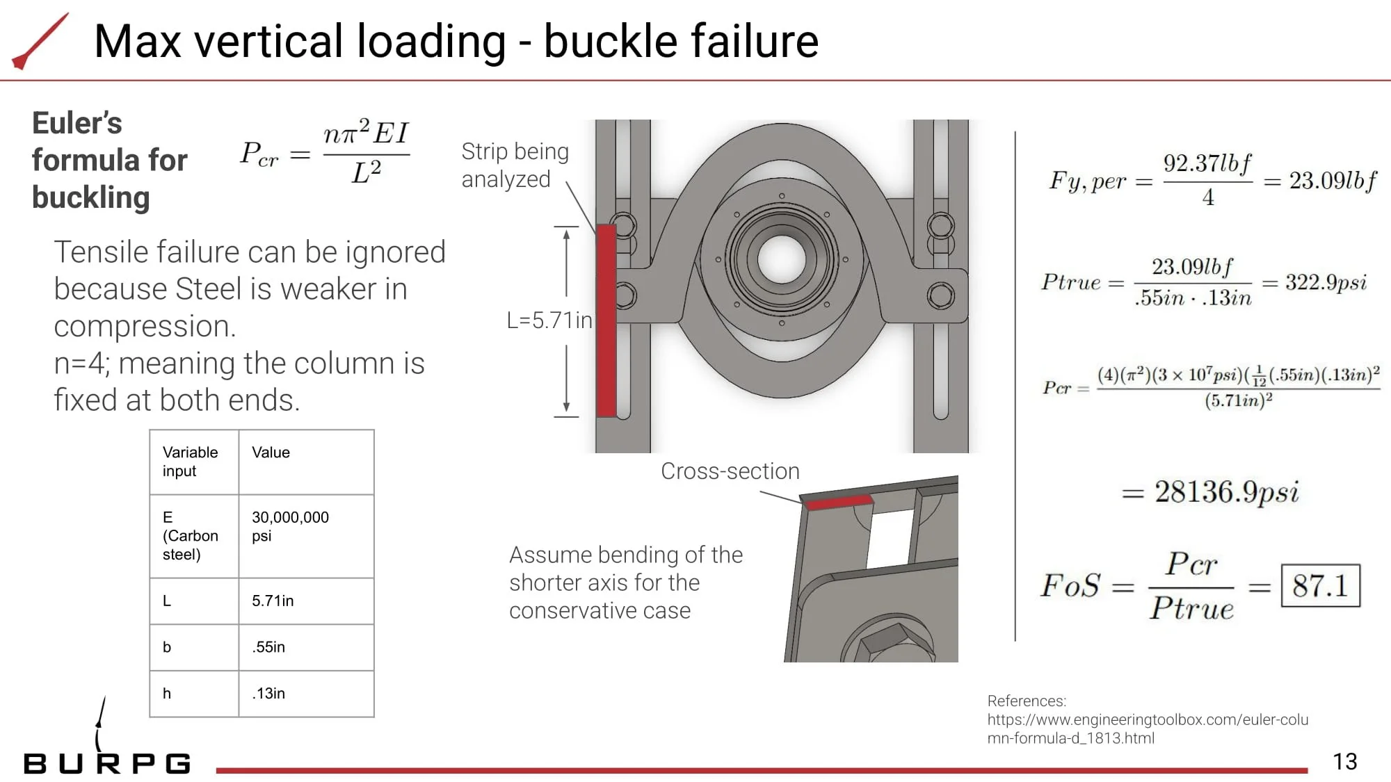
  3. Vertical Strut Failure

    • If both pre-loads and the center fixture hold, buckling of the vertical struts becomes a potential concern.

    • Buckling resistance was analyzed to ensure sufficient factor of safety in the design.